Commercial pool code requirements
Commercial pool code requirements include general information of the typical building and safety for commercial pools listed below.
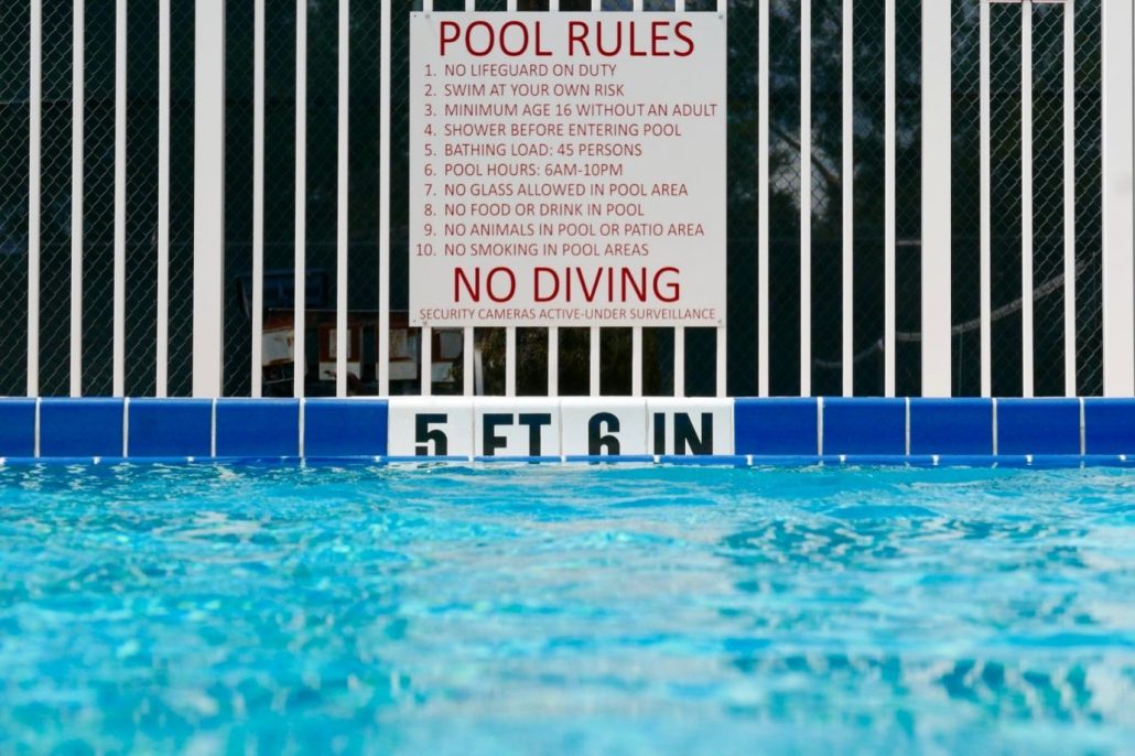
DEPTH MARKINGS
Location
The depth of water shall be plainly marked at or above the water surface on the vertical pool wall and on the edge of the deck at points of change in bottom slope, and spaced at not more than 25-foot (7.6-m) intervals measured peripherally. Markings shall be on both sides and ends of the pool. Where depth markings cannot be placed on the vertical walls above the water level, other means shall be used so that the markings will be plainly visible to persons in the pool
Design
Markings shall be indicated in feet and inches and may also be indicated in m. The depth markings shall include the units, i.e., “FEET,” or “FT.,” “INCHES” or “IN.,” and “METERS.” Depth markings (depths in numerals and units in letters) shall be of 4 inches (10 cm) minimum height and in color contrasting with the background.
LIFESAVING EQUIPMENT
Unit Composition One unit of lifesaving equipment shall consist of the following: Throwable Device – A U.S. Coast Guard-approved ring, 18 inches (46 cm) in diameter, or a throwing buoy, fitted with a ¼-inch (6 mm) diameter line with a length of 1.5 times the maximum width of the pool, or 50 feet (15 m), whichever is less.
Reaching Device
A life pole or a shepherd’s crook-type of pole, with blunted ends and a minimum length of 12 feet (3.7 m).
Units Required
One unit of lifesaving equipment shall be provided for each 2,000 square feet (186 m2) of water surface Area or major fraction thereof. A minimum of one unit shall be provided.
Location
Lifesaving equipment shall be mounted in conspicuous places, distributed around the swimming pool deck. Whenever lifeguard chairs are provided, each chair shall be equipped with one unit of lifesaving equipment.
FIRST AID EQUIPMENT
Every swimming pool shall be equipped with a long spine board with ties and a collar, and with a first aid kit which contains all of the following materials:
- two units – 1-inch (2.5 cm) adhesive compress
- two units – 2-inch (5.1 cm) bandage compress two units – 3-inch (7.6 cm)
- bandage compress two units – 4-inch (10 cm) bandage compress
- one unit – 3-inch by 3-inch (7.6 cm by 7.6 cm) plain gauze pad
- two units – gauze roller bandage
- one unit – eye dressing packet
- four units – plain absorbent gauze, ½ square yard (0.42 m2)
- three units – plain absorbent gauze, 24 inches (61 cm) by 72 inches (180 cm)
- four units – triangular bandages, 40 inches (101.6 cm/1.Om)
- one unit – bandage scissors, tweezers
- two units – disposable surgical gloves
- one unit – CPR face mask
- two units – protective face shield
FIRST AID ROOM
A swimming pool with a water surface area in excess of 4,000 square feet (370 m2) shall have a readily Accessible room or area designated and equipped for emergency care. The room or area shall have a cot, sink and telephone.
EMERGENCY TELEPHONE
Facilities which do not have a first aid room should have a telephone in or immediately adjacent to the pool area. The emergency number shall be posted at each pool area phone.
EMERGENCY EXIT
An emergency exit from the pool area shall be provided.
CONTENT
The posted rules shall include:
- Persons with infections not permitted.
- Do not bring food, drink, gum or tobacco or tobacco products into the pool enclosure.
- Shower before entering and after use of toilet facilities.
- No running or rough play.
- No diving, or no diving except in designated diving areas.
- No containers made of glass or shatterable plastic.
- Persons with a disease which can be transmitted through pool use shall not use the pool.
ADDITIONAL RULES
Whenever the regulatory authority determines that additional rules are needed to protect the health and safety of patrons, the management shall post and enforce such rules.
WARNING SIGNS
Whenever the pool area is opened for use and no lifeguard service is provided, warning signs shall be placed in plain view of the entrances and inside the pool area which state, “WARNING – NO LIFEGUARD ON DUTY” with clearly legible letters at least 4 inches (10 cm) high. In addition, the signs shall also state in clearly legible letters at least 2 inches (5.1 cm) high, “NO SWIMMING ALONE. CHILDREN AND NON-SWIMMERS SHALL NOT USE THE POOL UNLESS ACCOMPANIED BY A RESPONSIBLE ADULT.”
Commercial pool code ladders steps rails
General information of the typical building and safety codes for the ladders, steps and rails in a commercial swimming pool.
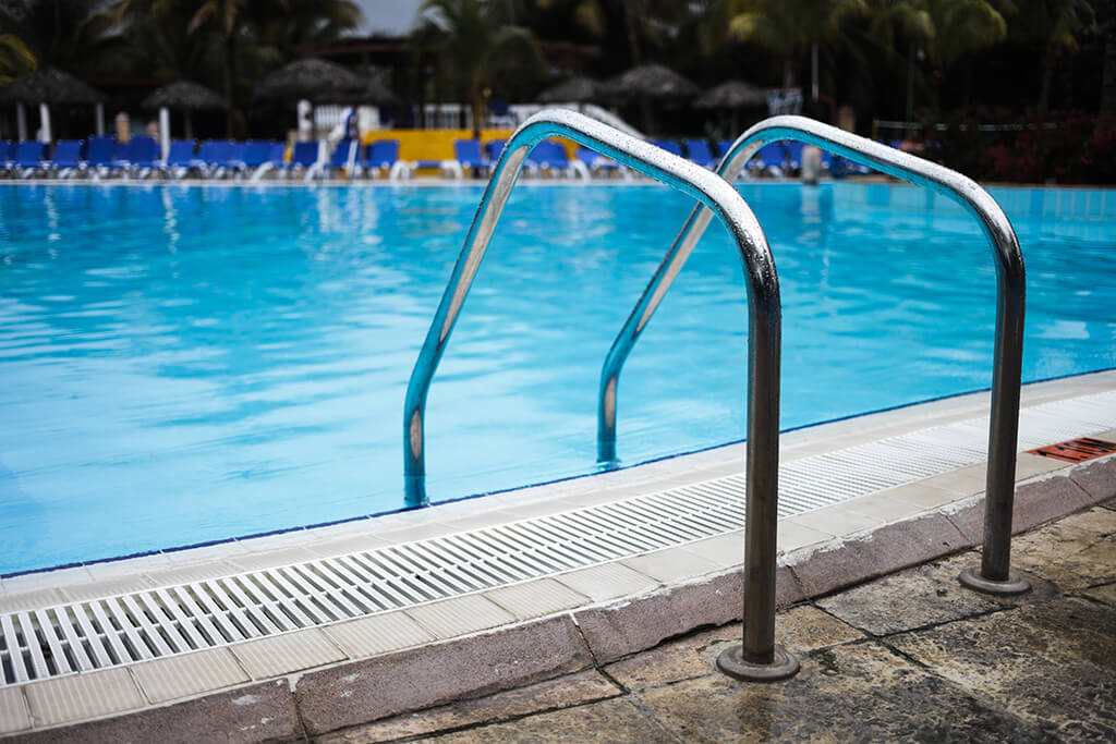
Location
Recessed steps, ladders, or stairs for swimming pools shall be provided at the shallow end. Ladders or recessed steps shall be provided at the deep end. If the pool is over 30 feet (9.1 m) wide, such steps, ladders, or stairs shall be installed on each side.
Ladders
Pool ladders shall be corrosion-resistant and shall be equipped with slip-resistant treads. All ladders shall be so designed as to provide a handhold. There shall be a clearance of not more than 6 inches (15 cm) nor less than 3 inches (7.6 cm) between any ladder and pool wall. Treads shall be no more than 12 inches (30 cm) apart.
Recessed Steps
Recessed steps shall be readily cleanable, slip-resistant, and shall be arranged to drain into the pool. Recessed steps shall have a minimum tread of 5 inches (13 cm) and a minimum width of 14 inches (36 cm). Steps shall be no more than 12 inches (30 cm) apart.
Handrails
Where recessed steps or ladders are provided, there shall be a handrail at the top of each side thereof, extending over the coping or edge of the deck.
Stairs and Stair Handrails
Where stairs are provided, they shall be located diagonally in a corner of the pool or be recessed. Handrails shall be provided at stairs such that all stair areas are within reach of a handrail. Stairs shall have slip-resistant finish, a minimum tread of 12 inches (30 cm), and a maximum rise of 10 inches (25 cm).
SWIMMING POOL SOURCE WATER SUPPLY AND WASTE WATER DISPOSAL
WATER SUPPLY
Water supplied to a public swimming pool and all related plumbing fixtures, including drinking fountains, lavatories and showers, shall at all times meet the quality standards of the appropriate regulatory agency.
CROSS-CONNECTION CONTROL
All portions of the water distribution system serving a public swimming pool and related facilities shall be protected against backflow and back siphonage. Water introduced into the pool, either directly or to the recirculation system, shall be through an air gap or an appropriate approved backflow preventer as required by the appropriate regulatory agency.
SANITARY WASTES
An approved method for disposing of sanitary sewage shall be provided at a public swimming pool. Where available, a municipal sanitary sewerage system shall be used. If an individual treatment system must be used, approval of the system must be obtained from the appropriate regulatory agency.
POOL WASTE WATER
Waste water from a public swimming pool shall be discharged in a manner approved by the appropriate regulatory agency.
BACKFLOW PREVENTION
In a public swimming pool, the recirculation system and pool deck drains shall be protected against the backflow of waste water in a manner approved by the appropriate regulatory agency.
CONDENSATE
Condensate shall not be introduced to the pool water or any part of the recirculation system.
HEAT EXCHANGERS
Any heating or cooling system which is connected in any way with the pool recirculation system shall contain only nontoxic heat transfer media, or a double-wall-type heat exchanger with vented intermediate space shall be used.
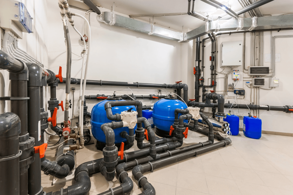
GENERAL SWIMMING POOL COMPONENTS & EQUIPMENT
Recirculation system components shall comply with NSF/ANSI Standard 50
POOL RECIRCULATION (TURN OVER) RATE
A swimming pool recirculation system shall be capable of processing one pool volume of water in six hours or less. A wading pool recirculation system shall be capable of processing one pool volume of watering two hours or less. Spa pools, wave pools and other special purpose pools shall have recirculation systems as required elsewhere in this standard.
MATERIALS of Components
Recirculation system components in contact with the swimming pool water shall be of non-toxic material, resistant to corrosion, and able to withstand operating pressures. Acceptable materials are copper, stainless steel, cast iron, ductile iron, plastics approved for potable water contact by the appropriate regulatory agency, or other materials suitable for potable water contact, subject to approval by the regulatory agency.
POOL PIPE SIZING
Swimming pool recirculation system piping shall be designed so that the water velocity shall not exceed 10 feet (3.0 m) per second on the discharge side of the recirculation pump, and 6 feet (1.8 m) per second in suction piping. Gravity piping shall be sized in accordance with accepted engineering practice with consideration of available head.
DRAINAGE AND INSTALLATION
All equipment and piping shall be designed and fabricated to drain completely by use of drain plugs, drain valves or other means. All piping shall be supported continuously or at sufficiently close intervals to prevent sagging. All suction piping shall be sloped in one direction, preferably toward the pump. All supply and return pipe lines to the pool shall be provided with insertable plugs or valves to allow the piping to be drained to a point below the frost line. Provision shall be made for expansion and contraction of pipes.
PIPE AND VALVE IDENTIFICATION
All exposed piping shall be clearly marked to indicate function. All valves shall be marked to indicate use.
OVERFLOW SYSTEMS
All pools shall be designed to provide continuous skimming (removal of surface water). Makeup water supply equipment shall be provided to maintain continuous skimming.
Gutters (Perimeter Overflow Systems)
The gutter shall extend around the full perimeter of the swimming pool except at stairways and ramps entering the swimming pool. It shall be level within a tolerance of plus or minus 1/8 inch (3 mm). Piping connections shall be provided to permit water to flow from overflows to waste, as well as to the recirculation system.
Size and Shape of Deck Drains
The gutter system shall be designed to allow continuous removal of water from the pool’s upper surface at a rate of at least 100 percent, and preferably 125 percent, of the recirculation rate. The gutter shall be designed to serve as a handgrip and to prevent entrapment of arms or legs. It shall permit ready inspection, cleaning and repair.
Electrical Receptacle Outlets
Drop boxes, converters, return piping or flumes used to convey water from the gutter shall be designed to handle at least 100 percent, but preferably 125 percent, of the recirculation rate. Drainage shall be sufficient to minimize flooding and prevent backflow of skimmed water into the pool
Surge Capacity
All overflow systems shall be designed with an effective surge capacity of not less than 1 gallon for each square2foot (41 L/m) of pool surface area. Surge shall be provided within a surge tank, in the gutter or filter above the normal flow line, or elsewhere in the system. Surge tanks, gutters and filter tanks should have overflow pipes to convey excess water to waste. Surge tanks shall be provided with means for complete draining. In-pool surge is allowed only with an engineered perimeter gutter system which includes an integral surge weir for each 500 square feet (46 m2) of water surface, and a tank to allow balancing of main drain and gutter flows.
Pool Surface Skimmers
The use of skimmers shall be limited to 2,000 or less square2feet (186 m or less) of surface area, and should be limited to widths of 30feet (9.1 m) or less.
Construction
Skimmers shall be installed in the pool walls, be sturdy, and be constructed of corrosion-resistant materials. Surface skimmers shall be of a type acceptable to the regulatory agency.
Number of Pool Skimmers
At least one surface skimmer shall be provided for each2500 square feet (46 m) of surface or fraction thereof. Additional skimmers may be required to achieve effective skimming. At least two skimmers should be provided.
Location of Skimmers
Skimmers shall be so located as to provide effective skimming of the entire water surface with minimum interference and short-circuiting.
Flow Rate of Skimmers
Skimmers shall provide for a flow-through rate of 30 gallons per minute (1.9 L/s), or 3.75 gallons per minute per lineal inch (93 mL/s/cm) of weir, whichever is greater.
Control of Skimmers
Skimmers shall have weirs that adjust automatically and operate freely and continuously with variations of at least 4 inches (10 cm) in water level. All skimmed water shall pass through an easily removable and cleanable basket or screen before encountering control valves or entering the pump suction line. Each skimmer shall be equipped with a device to control flow. If a skimmer is connected directly to the recirculation pump suction pipe, it should include a device to prevent an airlock in the suction line. If equalizer pipes are used, they shall pass an adequate amount of water to meet pump suction requirements should the water in the pool drop below the weir level. The equalizer pipes shall be located at least 1 foot (30 cm) below the lowest overflow level of the skimmer. A valve or equivalent device that will remain tightly closed under normal operating conditions, but automatically opens when the water level drops below the minimum operating level of the skimmer, shall be provided on each equalizer pipe.
Balancing Intake (Suction)
The recirculation system must be balanced to provide for optimum and uniform skimming. Floatation testing should be used for this purpose.
MAIN DRAIN SYSTEM (Suction)
Main drains of the pool shall be installed in the pool floor at the deepest point.
Design and Location
The main drain shall be designed to protect against suction entrapment; one or more of the following arrangements shall be used:
Multiple Drains
Two or more main drains shall be installed. The drains shall be at least 3 feet (91 cm) apart, shall be connected in parallel, and shall not permit any drain to be individually valve off.
Single Drain
A single main drain shall have a total area of at2least 144 square inches (930 cm).
Antivortex Covers Spacing
The drains shall not be greater than 20 feet (6.1 m) on centers, and an outlet shall be provided not more than 15 feet (4.6 m) from each side wall.
Antivortex Covers on Gratings
Main drains shall be protected by antivortex covers or gratings. The open area shall be large enough so the velocity does not exceed 1½ feet (46 cm) per second through the grating. Openings in grates shall not be over 1/2-inch (13-mm) wide. Gratings or drain covers shall not be removable without the use of tools.
Pool Piping
The piping shall be designed to carry 100 percent of the recirculation rate, and shall be equipped with a valve.
PUMPS AND STRAINERS
Pool Strainers
Strainers shall be provided through which all water shall pass before entering the pump. The strainers shall be of rigid construction, fabricated of corrosion resistant material, and sufficiently strong to prevent collapsing when clogged. The openings shall be no greater than 1/8 inch (3 mm) in any dimension. The total clear area of all openings shall be at least four times the area of the connecting pipe. The strainer shall have a quick-opening cover. Spare strainer baskets shall be provided. In systems where the filter is located on the suction side of the pump, strainers are not required.
Pool Pumping Equipment
A pump and motor shall be provided for the recirculation of the swimming pool water. The pump shall provide the recirculation flow rate required in Section 9.0.1, and the filter backwash rate required in Section 10.1.1 against the total dynamic head generated in the recirculation system. The pump shall be self-priming or shall be installed so that there is a net positive suction head on the pump inlet whenever the pump is operating. Multiple pumps should not be provided except for standby purposes. A gauge which indicates both pressure and vacuum shall be installed on the pump suction header, and a pressure gauge shall be installed on the discharge side of the pump. Pumps and motors shall be readily accessible for inspection and service.
FLOW RATE MEASUREMENT AND CONTROL
Flow Measurement
A flow meter or other device which gives a continuous indication of the flow rate in gallons per minute in the recirculation system shall be provided. If sand filters are used, a device should be provided to measure the backwash flow rate in gallons (liters) per minute. Flow meters shall have a measurement capacity of at least 1.5 times the design recirculation flow rate, and shall be accurate within 10 percent of the actual flow rate. The indicator shall have a range of readings appropriate for the anticipated flow rates, and be installed where it is readily accessible for reading and maintenance, and with straight pipe upstream and downstream of any fitting or restriction in accordance with the manufacturer’s recommendation.
Flow Regulation
A device for regulating the rate of flow shall be provided in the recirculation pump discharge piping.
POOL RETURN INLETS
The recirculation system shall have inlets adequate in design, number and location to insure effective distribution of treated water and maintenance of uniform disinfectant residual throughout the swimming pool. All other types of inlet systems not covered below shall be subject to approval by the regulatory authority.
Number of Inlets
Wall inlets shall be spaced not over 20 feet (6.1 m) apart, with one inlet within 5 feet (1.5 m) of each corner of the pool and one in each recessed step area.
Location of Inlets
Wall inlets shall be located at least 12 inches (30 cm) below the design water surface, or not less than 6 inches (15 cm) if designed to provide downward flow. Bottom inlets shall be uniformly spaced, with a separating distance of no greater than 20 feet (1.5 m), and with rows of inlets within 15 feet (4.6 m) of each side wall. In any pool over 60 feet (18 m) in width, bottom inlets should be provided.
Type Inlet fittings shall be of the adjustable rate-of-flow type. Directional flow inlets shall be used with skimmer-type pools. Inlets shall not extend from the floor or wall to create a hazard.
Testing
Dye testing (crystal violet or equivalent) should be performed to determine and adjust the recirculation pattern.